- Graphical Representation of the Parageneses of the Metabasites and Metapelites -
Graphical representations are proposed to plot the parageneses of the most common metamorphic rocks. So, the ACF diagram is used to represent the parageneses of magmatic mafic rocks (metabasalt, metagabbro), the metabasites. The A'KF and AFM diagrams are used to represent the parageneses of pelitic rocks, the metapelites.
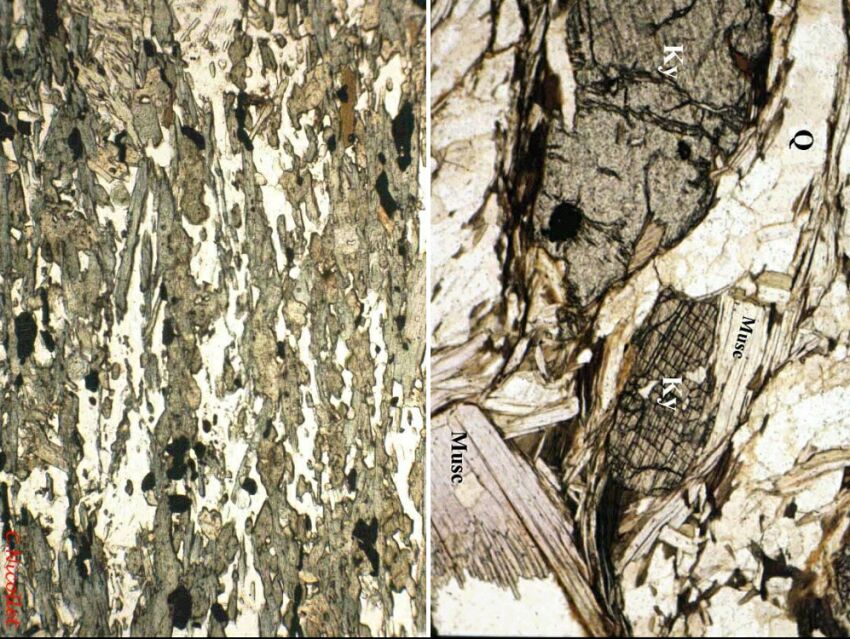
An amphibolite (left) and a metapelite (right) have different parageneses although both rocks have recrystallized under the same P T conditions: those of the amphibolite facies (microphotographs under PPL)
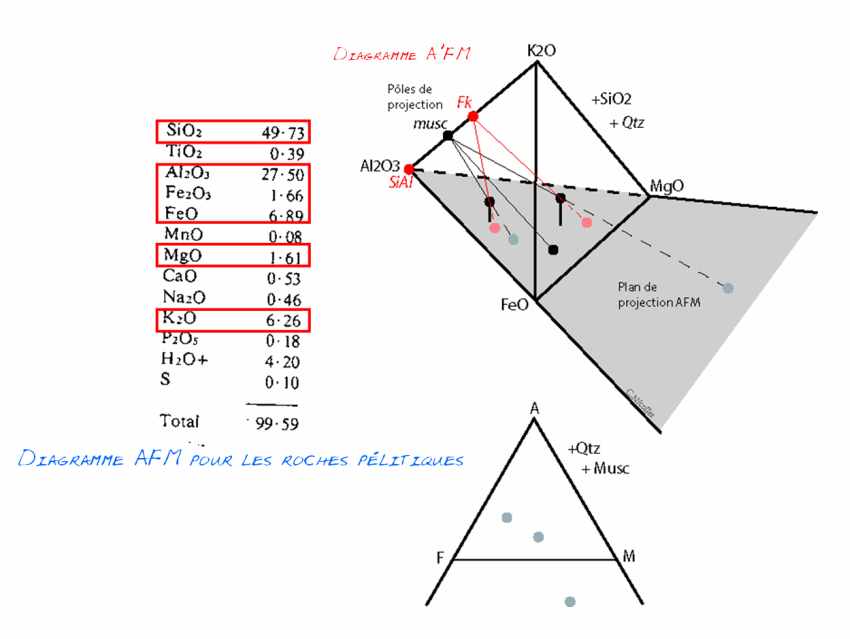
Parageneses of Metabasites : It is rare that only 3 chemical constituents (whose variations can be represented in a triangle; see previous exemple) reflect the composition of a rock. Here is the composition of a metabasite; eleven elements have significant concentrations. Five of them account for nearly 95% of the total. These are SiO2, Al2O3, FeO, MgO, CaO. For simplification, we will neglect the others.

The tetrahedron A(Al2O3) - C(CaO) - F(FeO+MgO)- S(SiO2) is representative of the composition of magmatic basic rocks. Some minerals of these rocks are plotted in the figure: Qtz for quartz, Opx for orthopyroxene, Cpx for clinopyroxene, Pl for plagioclase, Grt for garnet and Spl for spinel. The tie lines between these different minerals make it possible to define 4-mineral parageneses. On the left figure, these are: Qtz-Opx-Grt-Pl ; Qtz-Cpx-Opx-Pl ; Opx-Cpx-Pl-Grt ; Spl-Opx-Grt-Cpx ; Spl-Cpx-Grt-Pl (the tie lines involving the Spl are not shown for clarity, unless you use the 3D visualisation). On the right figure, Qtz-Opx-Grt-Cpx ; Qtz-Cpx-Grt-Pl ; Opx-Cpx-Pl-Grt ; Spl-Opx-Grt-Cpx ; Spl-Cpx-Grt-Pl. The 2 figures represent different metamorphic conditions. These are not easy to read. Therefore, we prefer to use a projection of this tetrahedron, from its summit S (where the Qtz is located), on its base: the ACF triangle . A convenient solution is the 3D visualisation!
However, it is difficult to graphically represent the variations of 5 constituents. It is therefore necessary to reduce this figure. The first solution is to consider FeO and MgO as a single component (Fe+Mg)O. Indeed, the addition of the FeO (or MgO) component to a purely magnesian (or ferric) system does not increase the number of minerals (as the phase rule states) :if iron is added to a forsterite (magnesian olivine), not two minerals are produced, but a "ferro-magnesian solid solution" olivine. There are still 4 components whose variations can be represented in a tetrahedron. However, it is difficult to visualise this figure on the 2-dimensional space of a sheet of paper. The solution is to project the volume of this tetrahedron onto a triangle. But the phase rule stipulates that 4 minerals constitute the paragenesis (= divariant assemblage with M=C) of the rocks to be represented in these figures, which is impossible without crossing tie lines. The solution is to choose one of the minerals of the paragenesis as the projection pole.In the case of the ACF triangle used to represent basic rocks, Quartz is the projection pole. For this reason, this mineral must absolutely be part of the paragenesis of the rocks presented in this diagram. This condition is recalled by writing Q next to the diagram.

The triangular diagram A(Al2O3)
- C(CaO) - F(FeO+MgO) is a projection of the
tetraedron S(SiO2)ACF from the apex S where the quartz is located (Q). For the sake of clarity, only the parageneses containing the Q are shown.As an example, I have drawn the paragenesis O-C-P-G from the previous figure: the dashed line CG is "hidden" by the planes O-C-P and O-G-P.
The 2 triangles represent respectively the Low P and Intermediate P granulite facies. We switch from one to the other by changing the O-P tie line to the C-G line: we cross the univariant equilibrium Opx + Pl = Cpx +
Gt + Q.